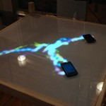
 TrafficFlow is an installation-based table which visualizes wireless traffic on a local network as gracefully flowing rivers of light. It is a collaborative project between Ameya Mhatre and myself created for our midterm project in the Spring 2009 Spatial Media class at ITP.
Each user on a network has an individual connection to the internet and may have a conceptual model of personalized “tube”. However, all traffic on a typical network shares the same infrastructure and commingles at some point, and if unencrypted, is available to any other member of the network. TrafficFlow aims to make visible this hidden connection.
 Connecting to the table’s public network begins the process. The user is directed to a welcome page and asked to place their device on the table, which creates a glowing circle around it. After the table detects the device, they are prompted to confirm that the highlighted device is theirs. As soon as they affirm their connection the circle disappears and their traffic begins to flow. We are looking to show the data as energy – something almost alive.
![]() The prototype still needs significant work in making the device capturing more robust, but the proof-of-concept is functional – and is demonstrated in the below video. Without getting too technical, the system uses several separate systems to function. A router with a custom Linux firmware based on DD-WRT handles the network connections, captive portal and packet sniffing. A Java applet and php script parses the packet output and provides web-based activation which populates a mysql database. The main application is written in C++ using the openFrameworks, openCV and mysql++ libraries. Ameya did the web and database stuff and I focused on the visualization/camera vision software. This is the most extensive software that I’ve written so far, but it’s been worth the work.
The prototype still needs significant work in making the device capturing more robust, but the proof-of-concept is functional – and is demonstrated in the below video. Without getting too technical, the system uses several separate systems to function. A router with a custom Linux firmware based on DD-WRT handles the network connections, captive portal and packet sniffing. A Java applet and php script parses the packet output and provides web-based activation which populates a mysql database. The main application is written in C++ using the openFrameworks, openCV and mysql++ libraries. Ameya did the web and database stuff and I focused on the visualization/camera vision software. This is the most extensive software that I’ve written so far, but it’s been worth the work.
 The table was custom built by several of us in the Spatial Media class. It has a plexiglass surface with a sheet of mylar for diffusion. It provided for under sensing with an IR camera and under projection, using a mirror to bounce the image off the floor. For most of us it was the first interactive surface that we’ve worked with and was challenging. The results of the prototype table are somewhat frustrating, but I think it could be made much more robust with more refinement. A good learning experience.
Enjoy the videos.
Implementation and Conceptual Notes

The table is circular with a smooth surface. User places an internet connected device on the table (mobile phone, PDA, laptop). After visiting the project’s website with the device and performing a brief initialization, particles representing internet traffic emanate from the device and begin to swarm off to the center of the table, where they become obscured in “the cloud”. As data flows into and out from the device, particles will flow between the cloud and the device. The movement of the particles will follow some type of fluid dynamics, tracking gracefully as the user moves their device. As the device is lifted from the table, the flow will cease.
Each particle represents packets of TCP/IP data. The particles will be color-coded by data type (web, e-mail, ftp, torrent, tcp overhead) and may be strung together to indicate groups of related packets in a data stream.
Methods:
Blob / Edge detection for devices on the table.
Packet Sniffing (Carnivore / libpcap) to watch network traffic / power visualization
Ajax web application to register users (associate IP with physical footprint of device)
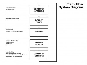
System Diagram:
particle system visualization
projector (spec. TBD)
projection surface (allowing for rear projection)
camera with IR emitter (location of emitter TBD)
sensing (IR, WiFi traffic)
Procedural Direction:
1. user joins our public network
*. user places device on surface
*. user instructed to visit initialization site
4. site asks user to hit the connect button
5. site recognized users IP / UserAgent string
6. visual confirmation, ensuring the correct device is correlated with the IP
7. association is made
8. start sniffing packets
a. read packet header
b. determine source, destination, data type (as inferred by port number)
c. pass this data to visualization in the form of parameters
9. begin visualization
10. if blob of associated device is lost, the ajax interface asks the user if they wish to reconnect
Points of Failure:
– confusion for those connected to the internet via mobile data service (GPRS, Edge, 3G)
– simultaneous user logo
– inability to maintain tracking of devices
Leave a Reply
You must be logged in to post a comment.