So, Tom asked us to try to figure out how the circuit in the 24 switch pixel works. It’s an array of 24 physical switches arranged in three banks of eight switches which enable the user to control an RGB LED in a manner similar to 24-bit digital color.
He told us that the circuit was entirely analog without any microcontroller. We had worked with parallel switches so that implied a hint to me as to how the circuit was able to vary the current.
This exercise took me a long way, only to end up very close to the beginning.
So, I knew that the switches were designed to act like bits of binary data:
2^0,   2^1,   2^2,    2^3,    2^4,    2^5,     2^6,    2^7
0|1,   0|2,   0|4,    0|8,    0|16,   0|32,    0|64,   0|128
I took this to mean that each switch doubles the resistance, or halves the current of the switch before it. Using the equation for Equivalent Resistance:
1 / Req = 1 / R1 + 1 / R2 + 1 / R3 + …
So, using the Equivalent Current formula, with 8 switches, each doubling in resistance, we get:
1/Req = 1/R + 1/2R + 1/4R + 1/8R + 1/16R + 1/32R + 1/64R + 1/128R
1/Req = 255/128R
R = 1.9921875 * Req
And then, the current can be determined
C(total) = V / Req
For instance…if the RGB LED draws 20 mA, then the resistance across it would be 250 ohms at 5V, right?
R = 1.9921875 * 250 Ohm ~ 500 Ohm
R1 = 500, R2 = 1k, R3 = 2k, R4 = 4k, R5 = 8k, R6 = 16k, R7 = 32k, R8 = 64K
When they are all on the Req = 250Ohm.
5V/250Ohm = 20 mA which is the full current draw for the LED.
Just R1 on, the Req = 500 Ohm = 5V / 500 Ohm = 10mA
which is about half the draw, and will be about half the brightness.
Ok, maybe not. The page for the 24 switch pixel has mention of a resistor ladder. Research on this leads me to believe that this is much simpler and is likely the solution. Schematic from wikipedia:

So, without REALLY knowing if it’s correct, I’m going to use the R and R2 values from the above equation to build the resistor ladder. (thinking about it after the fact, I could likely have used R=250 ohm rather than 500/1k.) Anyway, it did work:

The voltage steps can be determined by the equation:
VOUT = VREF x MaxVAL / 2^N
Vout = +5V * 31/32 = 4.84V
Vout = +5V * 15/32 = 2.34V
Vout = +5V * 7/32 = 1.09V
Vout = +5V * 3/32 = 0.46V
Vout = +5V * 1/32 = 0.15V
Vout = +5V * 0/32 = 0V
I don’t know if this is correct, but the resistor ladder did function as expected.
Oh, right, it’s not voltage but current that’s being altered, correct? Here are current readings using a multimeter:
5 bit resistor ladder
using 500/1k resistors
Measured from ground to LED’s cathode.
bits 0-3: 2.84
bits 0-2: 1.70
bits 0-1: 0.97
bit 0: 0.28
bit 1: 0.57
bit 2: 0.90
bit 3: 1.40
bit 4: 2.42
total current: 5.75 mA
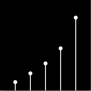
Plot of the above current draw values. Depicts an exponential relationship.

Least significant bit on.

All bits on.

Leave a Reply
You must be logged in to post a comment.